Welding Symbols Edge-to-Edge Guide
Welding symbols are crucial to the function of the weldments. Without adequate welding symbols or proper interpretation, a weldment may not operate adequately or could fail in the field. Weld symbols when appropriately applied to drawings and correctly interpreted offer a convenient way of controlling welding of a particular joint. The need for consistency on both the application of welding symbols to engineering drawings and the accurate interpretation by welding staff directly involved in manufacturing or construction guide to the development of a standard for welding operations. The current standard for welding symbols was originated by the American Welding Society and approved by the American National Standards Institute as ANSI/AWS A2.4, Standard tine for Welding and Nondestructive Examination. Therefore, there’re often several ways to specify each weld. Also, because a cost is a consideration and is related to the specific welding equipment that is used, the detail of joint geometry will vary from one manufacturer to another.
Arrow
The arrow is a significant part of every weld symbol and must point to the joint to be welded. The joint side to which the arrow points is called the arrow side of the joint while the opposite side of the joint is known as the other side of the joint. Usually, only limited space is available on a drawing for welding blueprint symbols. To minimize the number of welding symbols, it's allowed to use more than one arrow in each welding symbol if every joint to which arrow is pointing will be weld in precisely the same way. Since a welding symbol defines welding of only the joint to which an arrow is pointing and change in geometry or a change of direction forms the end of a joint, a multiple arrow welding symbol can be handy, especially around closed corners.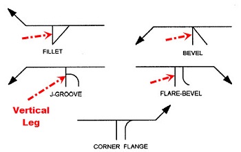
Reference Line
The reference line is a straight line, drawn horizontally on a blueprint, and connected to the arrow. The arrow may be linked to either end of the straight line. The blueprint of operations required to produce a designated weld isn't specified by the universal single-reference-line welding symbol. For instance, if welding is to be done on both the arrow and other sides of a joint, a single-reference-line welding symbol doesn't indicate which side of the joint is to be welded first. De facto, the symbol doesn’t specify completion of the welding from one side before the welding on the opposite side.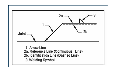
If the order of operations requires to be defined, a multiple-reference-line welding symbol may be applied. Two or more reference lines may be linked to the same arrow, with the reference line closest to the arrow pointing the first operation, tracked by the trail of reference lines reading downward or upward from the arrow.
Tail
The tail is drawn as a less-than (<) or greater than the (>) symbol, connected at the end of the reference line opposite the arrow. Reference to the approved WPS (welding procedure specification) is an example of information appropriate in the tail of a welding symbol. Welding procedure speciation can include all of the details applicable to a particular joint. Therefore, a welding symbol comprised of an arrow, reference line, tail, and appropriate WPS label would be sufficient to specify the welding of the joint altogether. The welding process is often designated by entering process specification letters in the tail of the welding symbol.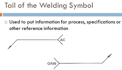
Weld-All Around Symbol
The specification to weld all around specifies that the weld is made to encapsulate the entire joint. In welding of circular joint, the weld all around symbol isn't needed. This symbol consists of a circle that is placed over the intersection where the end of the reference line meets the arrow.Field Weld
It’s a weld made at a location other than a shop or the place of initial construction. The field weld symbol composed of a flag that is positioned at the junction where the end of the reference line “faces” the arrow.Fillet Weld
As the symbol suggests, the filet is roughly triangular in profile, even though its form isn’t every time a right triangle or an isosceles triangle. The vertical leg of the triangle is standardly drawn on the left side of the symbol, despite the orientation of the weld. The leg size is always written to the left of the weld symbol. If the 2 legs of the weld are the same size, only one dimension is given. If the weld has unequal legs, both dimensions are given. If no length is specified, then the weld is placed between specified dimension lines or between those points where a sudden change in the weld direction may happen.Groove Weld
The groove weld is commonly applicated to form the edge-to-edge joints, although it’s also often applied in joints between flat and curved pieces. With the variety of the groove weld symbols, there’re many ways to make a groove weld. The disparities depend mostly on the geometry of the parts to be joined and the prep of their edges. Weld metal is located within the groove while penetrates and fuse with the base metal to create the joint.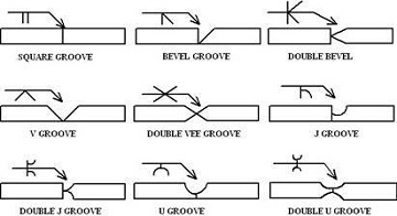
These are the listed types of groove weld:
- Square Groove Welds: The groove weld is created by either a tight fit or a slight separation of the edges;
- V-Groove Welds: The edges of both bars are rounded, either singly or doubly, to form the groove;
- Bevel Groove Welds: The edge of one piece is left square while the edge of another piece is rounded. The bevel symbol’s vertical line is always outlined on the left side, no matter the orientation of the weld. The arrow points the direction of the piece that will be chamfer;
- U-Groove Welds: The edges of both pieces have a concave treatment;
- J-Groove Welds: The edge of the one piece is a concave while the other piece is left square. As with the slope, the vertical line is always outlined on the left side, and the arrow points to the piece that gets the edge treatment;
- Flare-V groove welds: It's typically applicated to join two curved or rounded parts.
- Flare Bevel Groove Weld: Flare bevel groove weld is standardly used to join a curved or round piece to a flat piece.
Plug and Slot Welds
These welds are used to join overlapping elements, elongated for slot welds and round for plug welds. Weld metal is deposited in the holes while penetrates and fuses with the base metal of the 2 pieces to form the joint.Weld Length
Any weld, except plug and spot welds, includes a length element. The weld length could be the entire length of the joint or some portion of the joint. Commonly, the weld length is located to the right of the weld symbol, while its width is written to the left. If a weld is needed to make a change in direction, a multi-arrow or added symbol should be applicated. For example, a groove weld, besides the weld symbol, length, pitch, and size may include the root opening, depth of the penetration, groove angle, and degree of any beveling needed on the base metal.Intermittent Welds
An intermittent weld or a skip weld consists of many welds placed on a joint, with unwelded spaces between each of the welds. The individual weld segments in an intermittent weld have a length and pitch component. For intermittent welds, the length of each part and the spacing of the welds are divided by a dash and placed to the right of the fillet weld symbol.Weld Contour Symbols
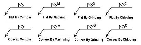
The contour of welds points the shape of its face. A weld with a convex contour has a face that extends out in a convex form from its toes. On the other hand, a weld with a concave contour has a concave face. Also, a weld with a flush contour has a flat look.Finish Symbols
Positioning a finish symbol next to the contour symbol specifies the technique of making the contour. The finish symbols are composed of letters. The letters and their corresponding methods are presented below.- G – Grinding;
- M – Machining;
- C – Chipping;
- R – Rolling;
- H – Hammering;
- P – Planishing;
- U – Unspecified.
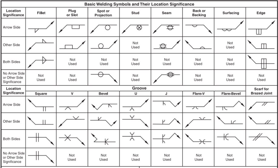
Basic Weld Symbols
Weld symbols are used to designate the welding processes applicated in metal joining operations, whether it is a shop or field weld, whether the weld is localized or all-around, and the contour of welds also. Follow basic weld symbols explained below.Basic Weld Symbols
Weld symbols are used to designate the welding processes applicated in metal joining operations, whether it is a shop or field weld, whether the weld is localized or all-around, and the contour of welds also. Follow basic weld symbols explained below.- Flow welding – FLOW;
- Flash welding – FW;
- Upset welding – UW;
- Percussion welding – PW;
- Induction welding – IW;
- Bare metal arc welding – MBAW;
- Gas shielded stud welding – GSSW;
- Submerged arc welding – SAW;
- Gas tungsten arc welding – GTAW;
- Gas metal arc welding – GMAW;
- Atomic hydrogen welding – AHW;
- Shielded metal arc welding – SMAW;
- Twin carbon arc welding – TCAW;
- Carbon arc welding – CAW;
- Gas carbon arc welding – GCAW;
- Shielded carbon arc welding – SCAW;
- Flux cored arc welding – FCAW;
- Nonpressure thermic welding – NTW;
- Pressure thermic welding – PTW;
- Pressure gas welding – PGW;
- Oxyhydrogen welding – OXW;
- Oxyacetylene welding – OAW;
- Air acetylene welding – AAW;
- Roll welding – RW;
- Die Welding – DW;
- Hammer welding – HW;